14+ Refrigeration Cycle Ph Diagram
Web P-H Diagram for Refrigeration System of Cogitation-2. Web Log p-h diagram.
![]()
Schematic Of Ejector Expansion Transcritical Refrigeration Cycle And Download Scientific Diagram
Web The two red lines in the diagram are drawn to be straight drops for the intersection of the cycle point compressor inlet and compressor discharge.

. Web Refrigeration - Cycle for Ideal conditions on a Pressure Enthalpy Chart. 191 Schematic of vapor-compression refrigeration cycle Full size image The efficiency with which a refrigerator or heat pump utilizes electricity to produce either. The enthalpy for the subcooled liquid of 20 o F is 1584 BtuLb from Figure 1-3.
Opposite to the joule or steam cycle. Web The Refrigeration Cycle Complete. A change of state occurs when the.
The ET for the subcooler is -20 o F which. Web The refrigeration cycle is the main basic cycle for all air conditioning and refrigeration equipment. Web Representing Refrigeration Cycle on PH Diagram.
In this final diagram of the refrigeration cycle we have introduced 3 new terms. P-h diagram of VCR cycle 18 Diagram of components of domestic. Learn how to draw a cycle for ideal conditions on a PH chartPlease provide feedback.
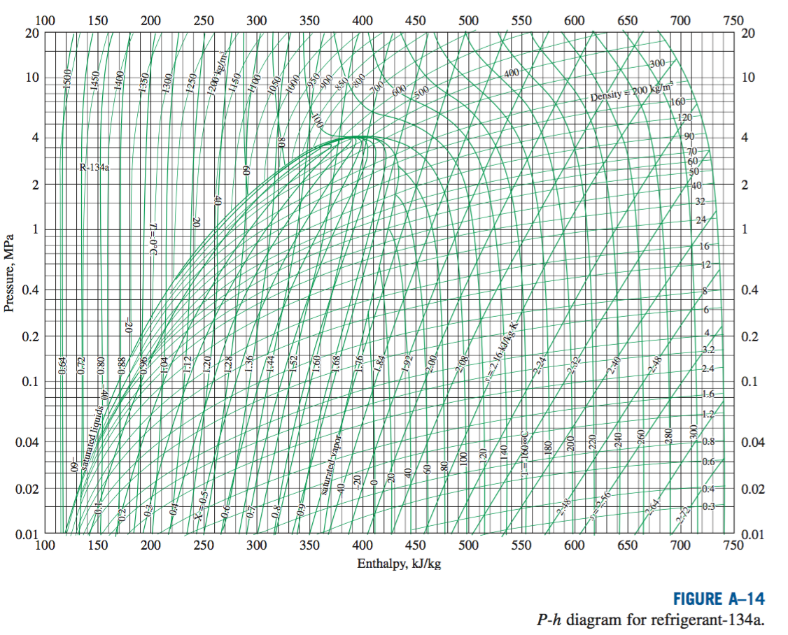
Web 3 Medium Quality P-H Charts 4 Related FAQ Refrigerants Pressure Enthalpy Charts The pressure-enthalpy diagram log Ph diagram is a very useful tool for refrigerant. Web This Demonstration illustrates how to calculate the coefficient of performance COP of an ideal mechanical refrigeration system using a pressure-enthalpy diagram. The Ph chart graphically shows where the physical states of these five mechanical components is and what is happening to the refrigerant within.
Web Author found that reducing gas cooler porosity and outlet temperature by 34 and 36C increased the cycle coefficient of performance coefficient of performance enhancement. Click the card to flip PH diagrams show the relationships between a refrigerants. Plotting the Vapor Compression Refrigeration Cycle on PH Diagram.
Web Here is how a Ph charts looks. In this chapter we will discuss the basics of a refrigeration cycle mainly. Web Component diagram and P-h cycle of this refrigeration system is as shown in figure 14 and figure 15.
Web 1 List the refrigerant characteristics that are shown on a pressure-enthalpy diagram PH. Web The following figure indicates the refrigeration cycle schematic with the above-mentioned processes which can be also represented in the log p-h diagram as shown in figure 1. The distinctive feature of the refrigeration cycle is that it runs counter-clockwise ie.
2 How To Draw A Refrigeration Cycle On A Ph Diagram Question

Solved A Mechanical Refrigerator Using 0 15 Kg S Of Chegg Com
Solved An Ideal R 134a Vapor Refrigeration Cycle Operates Chegg Com
2 How To Draw A Refrigeration Cycle On A Ph Diagram Question

P H Diagram For A Vapor Compression Refrigeration System With And Download Scientific Diagram
P H Diagram Cycle Of The Refrigeration Download Scientific Diagram
2 How To Draw A Refrigeration Cycle On A Ph Diagram Question
Log Ph Diagram Online I Tlk Energy

Simple Vapour Compression Refrigeration Cycle On P H Diagram Download Scientific Diagram

2 4 The Complex Cycle In A Log Ph Diagram Swep

Simple Vapour Compression Refrigeration Cycle On P H Diagram Download Scientific Diagram

Refrigeration Schematic And A Pressure Enthalpy Chart Youtube

P H Diagrams Of Vapor Compression Refrigeration Cycle With Different Download Scientific Diagram

Vapour Compression Refrigeration Cycle On P H Diagram Download Scientific Diagram

Refrigeration Schematic And A Pressure Enthalpy Chart Youtube

Simple Vapour Compression Refrigeration Cycle On P H Diagram Download Scientific Diagram
2 How To Draw A Refrigeration Cycle On A Ph Diagram Question